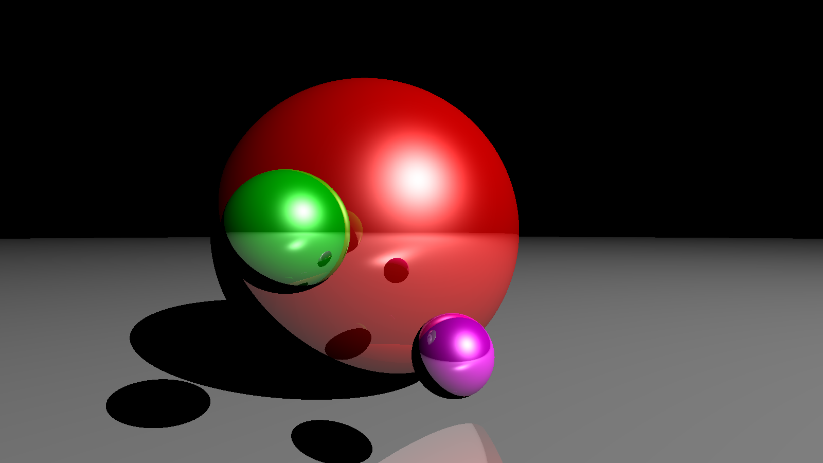
In this post I will explain how the ray tracing algorithm works and we'll implement it from scratch in Python to generate the image shown above, using only Numpy!
Prerequisites
We only need very basic vector geometry.
- Given two n-dimensional points [begin-latex-inline]A[end-latex-inline] and [begin-latex-inline]B[end-latex-inline], a vector that goes from [begin-latex-inline]A[end-latex-inline] to [begin-latex-inline]B[end-latex-inline] can be computed as the element-wise subtraction [begin-latex-inline]\overrightarrow{AB} = B-A[end-latex-inline]
- The length of a vector (the distance from the origin to the point representing the tip of the vector) is computed as [begin-latex-inline]\|x\| = \sqrt{x_1^2 + x_2^2 + \cdots + x_n^2}[end-latex-inline]
- A unit-vector is a vector of length 1: [begin-latex-inline]\|x\| = 1[end-latex-inline]
- Given a vector [begin-latex-inline]x[end-latex-inline], the unit-vector that points to the same direction as [begin-latex-inline]x[end-latex-inline] is obtained by dividing each component of [begin-latex-inline]x[end-latex-inline] by its norm: [begin-latex-inline]\dfrac{x}{\|x\|}[end-latex-inline]
- The dot product of two vectors [begin-latex-inline]u[end-latex-inline] and [begin-latex-inline]v[end-latex-inline] is [begin-latex-inline]\lang u,v \rang = u_1v_1 + u_2v_2 + \cdots + u_nv_n[end-latex-inline], and is equal to zero when [begin-latex-inline]u[end-latex-inline] and [begin-latex-inline]v[end-latex-inline] are perpendicular
- Solving a quadratic equation: [begin-latex-inline]ax^2 + bx + c = 0[end-latex-inline]
Ray Tracing Algorithm
In effect, ray tracing is a rendering technique that simulates the path of light and is able to produce images with a high degree of realism. More optimized variations of this algorithm are actually used in video games!
To explain the algorithm we need to setup a scene. In particular we need:
- A 3D space: we'll use [begin-latex-inline](x,y,z)[end-latex-inline] coordinates to position objects in space
- Objects in that space: we'll only deal with spheres
- A source of light: this will be a single point emitting light in all directions
- An "eye" or a camera to observe the scene
- A screen through which the camera will be observing the scene
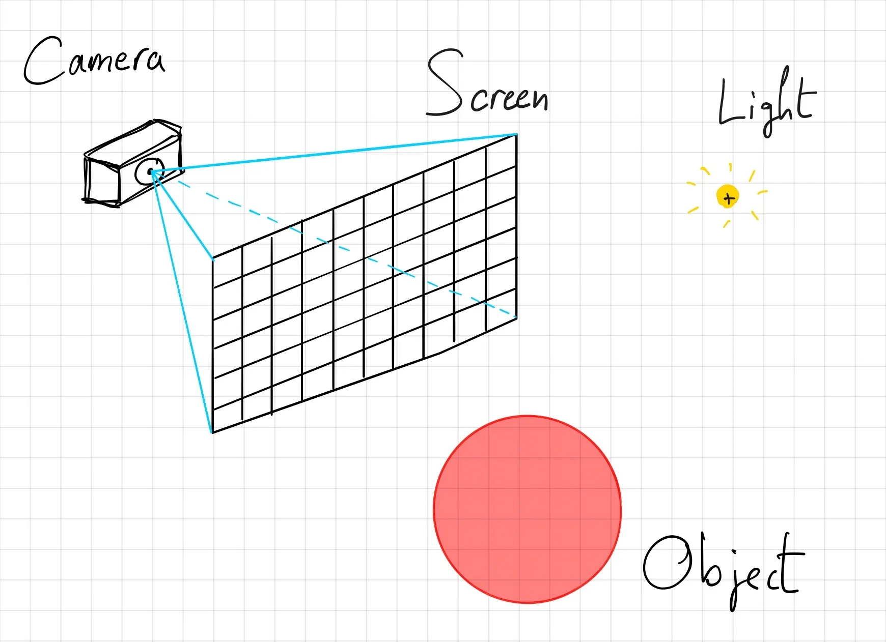
Given the scene, the ray tracing algorithm is as follows:
for each pixel p(x,y,z) of the screen:
  associate a black color to p
  if the ray (line) that starts at the camera and goes through p intersects any object of the scene:
    calculate the intersection point between the ray and the nearest object in the scene
    if there is no object of the scene in-between the intersection point and the light source:
      calculate the color of the intersection point and assign it to p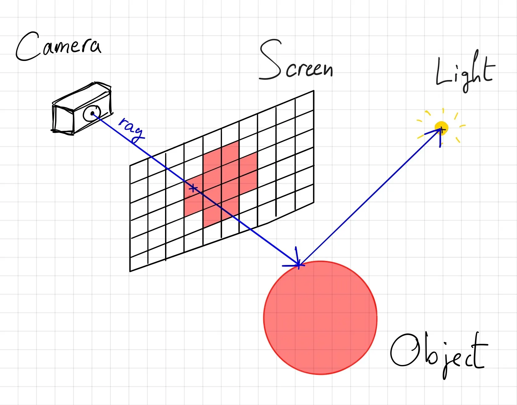
The whole process is purely geometrical, the only thing I didn't explain is how to calculate the color of the intersection point. We will see this in time. For now, just know there exist a physical model that describes how objects are illuminated when light strikes on them with a certain angle, intensity, etc.
Setting Up The Scene
First, we'll need to setup a scene. For now, we will decide where the camera and the screen are located. We can make things simple by aligning them with the unit axes.

The camera is located at [begin-latex-inline](0,0,1)[end-latex-inline] and the screen is part of the [begin-latex-inline](x,y)[end-latex-inline] plane. I arbitrarily spanned the screen from [begin-latex-inline]-1[end-latex-inline] to [begin-latex-inline]1[end-latex-inline] on the [begin-latex-inline]x[end-latex-inline]-axis, and the height of screen need to be calculated to respect the final aspect-ratio we want our image to have. As you can see in the code below, the size of the screen does not define the size of our final image since we can subdivide the screen into an arbitrary number of pixels.
import numpy as np
import matplotlib.pyplot as plt

width = 300
height = 200

camera = np.array([0, 0, 1])
ratio = float(width) / height
left, top, right, bottom = (-1, 1 / ratio, 1, -1 / ratio) # screen

image = np.zeros((height, width, 3)) # RGB image
for i, y in enumerate(np.linspace(top, bottom, height)):
    for j, x in enumerate(np.linspace(left, right, width)):
        # image[i, j] = ... compute the pixel color
        print("progress: %d/%d" % (i + 1, height))

plt.imsave('image.png', image)
If you run the script now, it'll produce a black image. Looking back at the pseudo-code algorithm, we are here:
✅for each pixel p(x,y,z) of the screen:
✅  associate a black color to p
☑️  if the ray (line) that starts at the camera and goes through p intersects any object of the scene:
☑️    calculate the intersection point between the ray and the nearest object in the scene
☑️    if there is no object of the scene in-between the intersection point and the light source:
☑️      calculate the color of the intersection point and assign it to p
Ray Intersection
The next step of the algorithm is:
First, we need to define the ray.
Ray Definition
We say "ray" but that's really just another word for "line". In general, whenever you code something that is geometrical, you should prefer vectors over actual line equations, they are easier to work with and much more stable numerically.
Since the ray starts at the camera and goes in the direction of the selected pixel, we can define a unit-vector that points to a similar direction:
Remember, camera and pixel are 3D-points. For [begin-latex-inline]t=0[end-latex-inline] you end up at the camera position, and the more you increase [begin-latex-inline]t[end-latex-inline] the further away you get from the camera in the direction of the pixel. This is a parametric equation, that yields a point along the line for a given [begin-latex-inline]t[end-latex-inline].
In general you can think of a ray as starting from an origin and going to a destination.
We define [begin-latex-inline]d[end-latex-inline] as the direction vector for convenience.
We can now complete the code and add the computation of the ray.
def normalize(vector):
    return vector / np.linalg.norm(vector)

# ...
for i, y in enumerate(np.linspace(top, bottom, height)):
    for j, x in enumerate(np.linspace(left, right, width)):
        pixel = np.array([x, y, 0])
        origin = camera
        direction = normalize(pixel - origin)

        # image[i, j] = ... compute the pixel color
        print("progress: %d/%d" % (i + 1, height))
Now that we have defined the ray, we need to compute the intersection with the objects of the scene... But there are no objects yet!
We said earlier we'll only have spheres, so let's define a Sphere!
Sphere Definition
A sphere of radius [begin-latex-inline]r[end-latex-inline] centered at [begin-latex-inline]C[end-latex-inline] is defined as the set of points that are at a distance [begin-latex-inline]r[end-latex-inline] from [begin-latex-inline]C[end-latex-inline]. Therefore, given the radius [begin-latex-inline]r[end-latex-inline] and center [begin-latex-inline]C[end-latex-inline] of a sphere, an arbitrary point [begin-latex-inline]X[end-latex-inline] lies on the sphere if and only if:
For convenience, we square both sides to get rid of the square root caused by [begin-latex-inline]\|X — C\|[end-latex-inline].
Let's define some spheres in a dictionary:
objects = [
  {'center': np.array([-0.2, 0, -1]), 'radius': 0.7},
  {'center': np.array([0.1, -0.3, 0]), 'radius': 0.1},
  {'center': np.array([-0.3, 0, 0]), 'radius': 0.15}
]
Now let's compute the intersection between the ray we computed earlier and a sphere from our list.
Sphere Intersection
We know the ray equation, and we know what condition a point must satisfy so that it lays on a sphere. We can substitute [begin-latex-inline]X[end-latex-inline] in the sphere equation with [begin-latex-inline]ray(t)[end-latex-inline] and solve for [begin-latex-inline]t[end-latex-inline]. This will answer the question:
This is an ordinary quadratic equation that we can solve for [begin-latex-inline]t[end-latex-inline]. Let's calculate the discriminant of that equation:
Since the direction vector [begin-latex-inline]d[end-latex-inline] is a unit-vector, we have [begin-latex-inline]\|d\| = 1[end-latex-inline]. Once the we calculate the discriminant [begin-latex-inline]\Delta[end-latex-inline], there are 3 possibilities:

We will only use the third case to detect intersections. We'll write a function that returns:
- [begin-latex-inline]t[end-latex-inline], the distance from the origin of the ray to the nearest intersection point if the ray intersects the sphere
Noneif there are no intersections
def sphere_intersect(center, radius, ray_origin, ray_direction):
    b = 2 * np.dot(ray_direction, ray_origin - center)
    c = np.linalg.norm(ray_origin - center) ** 2 - radius ** 2
    delta = b ** 2 - 4 * c
    if delta > 0:
        t1 = (-b + np.sqrt(delta)) / 2
        t2 = (-b - np.sqrt(delta)) / 2
        if t1 > 0 and t2 > 0:
            return min(t1, t2)
    return None
Note that:
- If
t1 < 0 and t2 < 0then it means the sphere is behind the camera - If
t1 < 0 and t2 > 0then it means the camera is within the sphere
Nearest Intersected Object
So far so good, we know how to compute a ray, we know how to check for intersections with spheres in the scene, now we have to complete the algorithm:
def nearest_intersected_object(objects, ray_origin, ray_direction):
    distances = [
        sphere_intersect(obj['center'], obj['radius'], ray_origin, ray_direction)
        for obj in objects
    ]
    nearest_object = None
    min_distance = np.inf
    for obj, distance in zip(objects, distances):
        if distance is not None and distance < min_distance:
            min_distance = distance
            nearest_object = obj
    return nearest_object, min_distance
Let's include that in the script:
import numpy as np
import matplotlib.pyplot as plt

def normalize(vector):
    return vector / np.linalg.norm(vector)

def sphere_intersect(center, radius, ray_origin, ray_direction):
    b = 2 * np.dot(ray_direction, ray_origin - center)
    c = np.linalg.norm(ray_origin - center) ** 2 - radius ** 2
    delta = b ** 2 - 4 * c
    if delta > 0:
        t1 = (-b + np.sqrt(delta)) / 2
        t2 = (-b - np.sqrt(delta)) / 2
        if t1 > 0 and t2 > 0:
            return min(t1, t2)
    return None

def nearest_intersected_object(objects, ray_origin, ray_direction):
    distances = [
        sphere_intersect(obj['center'], obj['radius'], ray_origin, ray_direction)
        for obj in objects
    ]
    nearest_object = None
    min_distance = np.inf
    for obj, distance in zip(objects, distances):
        if distance and distance < min_distance:
            min_distance = distance
            nearest_object = obj
    return nearest_object, min_distance

width = 300
height = 200

camera = np.array([0, 0, 1])
ratio = float(width) / height
left, top, right, bottom = (-1, 1 / ratio, 1, -1 / ratio) # screen

objects = [
    {'center': np.array([-0.2, 0, -1]), 'radius': 0.7},
    {'center': np.array([0.1, -0.3, 0]), 'radius': 0.1},
    {'center': np.array([-0.3, 0, 0]), 'radius': 0.15}
]

image = np.zeros((height, width, 3))
for i, y in enumerate(np.linspace(screen[1], screen[3], height)):
    for j, x in enumerate(np.linspace(screen[0], screen[2], width)):
        pixel = np.array([x, y, 0])
        origin = camera
        direction = normalize(pixel - origin)

        # get intersection distance with the nearest object in the scene
        nearest_object, min_distance = nearest_intersected_object(objects, origin, direction)
        if nearest_object is None:
            continue

        # compute intersection point between ray and nearest object
        intersection = origin + min_distance * direction

        # image[i, j] = ...
        print("%d/%d" % (i + 1, height))

plt.imsave('image.png', image)
We have actually completed 2 steps, we're almost there!
✅for each pixel p(x,y,z) of the screen:
✅  associate a black color to p
✅  if the ray (line) that starts at the camera and goes through p intersects any object of the scene:
✅    calculate the intersection point between the ray and the nearest object in the scene
☑️    if there is no object of the scene in-between the intersection point and the light source:
☑️      calculate the color of the intersection point and assign it to p
Light Intersection
So far, we know if there is a straight line that goes from the camera through the pixel and that intersects with an object of the scene. But we don't know if that point is receiving light at all, which will determine if it should be visible to us! Therefore, the next step is to check if there is no object of the scene in-between the intersection point and the light source.
Fortunately, we already have a function to help us: nearest_intersected_object(). Indeed, we want to know if the ray that starts at the intersection point and goes towards the light is intersecting an object of the scene. This is the same task as previously, we just need to change the ray origin and direction. But first, we need to define a light.
light = {'position': np.array([5, 5, 5])}Then,
# ...
intersection = origin + min_distance * direction

# check if intersection point is receiving light
intersection_to_light = normalize(light['position'] - intersection)
_, min_distance = nearest_intersected_object(objects, intersection, intersection_to_light)
intersection_to_light_distance = np.linalg.norm(light['position'] - intersection)
is_shadowed = min_distance < intersection_to_light_distance # make sure the object is in-between the intersection and the light (we don't care that an object is behind the light and intersecting with the ray)
Looks neat, right? Well this will not work! We need to make a slight adjustment.
If we use the intersection point as the origin of the new ray we might end up detecting the sphere where we currently stand as an object in between the intersection point and the light! A fix for that problem is to take a little step that gets us away from the surface of the sphere. We generally use a normal vector to the surface and take a little step in that direction.

Therefore, the correct code is:
# ...
intersection = origin + min_distance * direction

# check if intersection point is receiving light
normal_to_surface = normalize(intersection - nearest_object['center'])
shifted_point = intersection + 1e-5 * normal_to_surface
intersection_to_light = normalize(light['position'] - shifted_point)

_, min_distance = nearest_intersected_object(objects, shifted_point, intersection_to_light)
intersection_to_light_distance = np.linalg.norm(light['position'] - intersection)
is_shadowed = min_distance < intersection_to_light_distance

if is_shadowed:
    continue
✅for each pixel p(x,y,z) of the screen:
✅ associate a black color to p
✅ if the ray (line) that starts at the camera and goes through p intersects any object of the scene:
✅ calculate the intersection point between the ray and the nearest object in the scene
✅ if there is no object of the scene in-between the intersection point and the light source:
☑️ calculate the color of the intersection point and assign it to pBlinn-Phong Reflection Model
This is it, the last part. We know a light beam has stroke the object, and the reflection of the beam got straight into the camera. The question that remains is:
This is what the Blinn-Phong model attempts to answer.
According to this model, any material has 4 properties:
- Ambient color: base color an object has when indirect light hits it. It ensures objects of the scene are never completely black.
- Diffuse color: color perceived when direct light hits a surface and scatters equally in all directions. This is characteristic of matte or non-shiny surfaces like paper or chalk.
- Specular color: represents the bright, mirror-like reflection of a light source on a shiny surface. Think of the glint of light on a polished apple or a plastic toy. The appearance of the specular highlight depends on the viewing direction.
- Shininess: a coefficient representing the size of the specular highlight
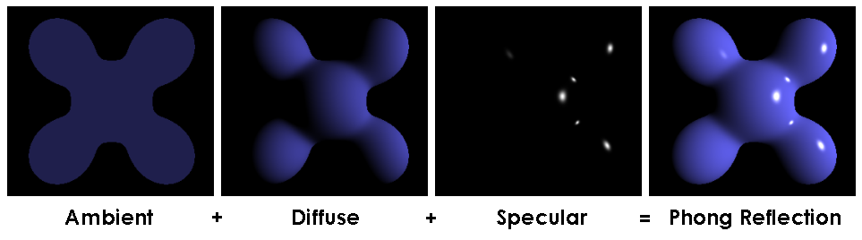
So every object and light of the scene must have these 4 properties:
objects = [
    {'center': np.array([-0.2, 0, -1]), 'radius': 0.7, 'ambient': np.array([0.1, 0, 0]), 'diffuse': np.array([0.7, 0, 0]), 'specular': np.array([1, 1, 1]), 'shininess': 100},
    {'center': np.array([0.1, -0.3, 0]), 'radius': 0.1, 'ambient': np.array([0.1, 0, 0.1]), 'diffuse': np.array([0.7, 0, 0.7]), 'specular': np.array([1, 1, 1]), 'shininess': 100},
    {'center': np.array([-0.3, 0, 0]), 'radius': 0.15, 'ambient': np.array([0, 0.1, 0]), 'diffuse': np.array([0, 0.6, 0]), 'specular': np.array([1, 1, 1]), 'shininess': 100}
]

light = {'position': np.array([5, 5, 5]), 'ambient': np.array([1, 1, 1]), 'diffuse': np.array([1, 1, 1]), 'specular': np.array([1, 1, 1])}
In this example, the spheres are red, magenta, and green respectively.
Given these properties, the Blinn-Phong model calculates the illumination of a point as follows:
Where,
- [begin-latex-inline]k_a, k_d, k_s[end-latex-inline] are the ambient, diffuse, specular properties of the object
- [begin-latex-inline]i_a, i_d, i_s[end-latex-inline] are the ambient, diffuse, specular properties of the light
- [begin-latex-inline]L[end-latex-inline] is the direction unit-vector from the intersection point towards the light
- [begin-latex-inline]N[end-latex-inline] is the unit-vector normal to the surface of the object at the intersection point
- [begin-latex-inline]V[end-latex-inline] is the direction unit-vector from the intersection point towards the camera
- [begin-latex-inline]\alpha[end-latex-inline] is the shininess of the object's specular highlights
# ...
if is_shadowed:
    break

# RGB
illumination = np.zeros((3))

# ambiant
illumination += nearest_object['ambient'] * light['ambient']

# diffuse
illumination += nearest_object['diffuse'] * light['diffuse'] * np.dot(intersection_to_light, normal_to_surface)

# specular
intersection_to_camera = normalize(camera - intersection)
H = normalize(intersection_to_light + intersection_to_camera)
illumination += nearest_object['specular'] * light['specular'] * np.dot(normal_to_surface, H) ** (nearest_object['shininess'] / 4)

image[i, j] = np.clip(illumination, 0, 1)
Notice that at the end, we clip the color between 0 and 1 to make sure it's in the correct range. That's it!
✅for each pixel p(x,y,z) of the screen:
✅  associate a black color to p
✅  if the ray (line) that starts at the camera and goes through p intersects any object of the scene:
✅    calculate the intersection point between the ray and the nearest object in the scene
✅    if there is no object of the scene in-between the intersection point and the light source:
✅      calculate the color of the intersection point and assign it to p
Run The Code!
Increase width and height for a higher resolution (at the cost of your time).
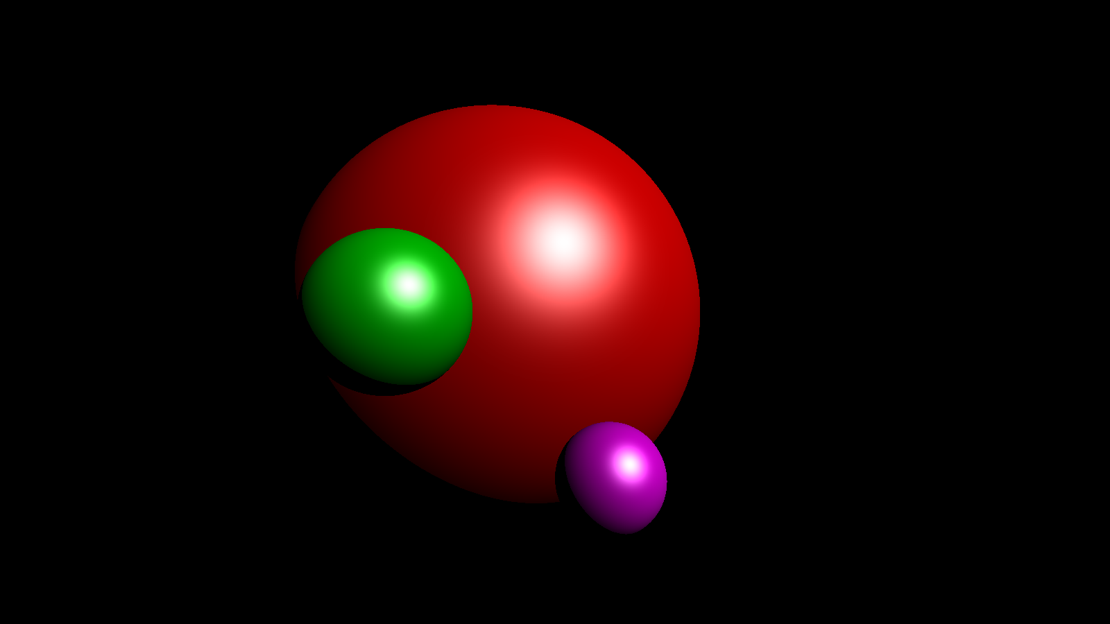
You'll probably notice 2 differences with the cover image.
- The grey floor is missing
- There are no reflections (mirror effect) in this picture
Fake Plane
Ideally, we would create another type of object, a plane, but because we're lazy we can simply use another sphere. How? Well, if you're standing on a sphere that has a large enough radius, then you'll feel like you're standing on a flat surface. Just like earth!
Add this sphere to your list of objects, and render again!
{'center': np.array([0, -9000, 0]), 'radius': 9000 - 0.7, 'ambient': np.array([0.1, 0.1, 0.1]), 'diffuse': np.array([0.6, 0.6, 0.6]), 'specular': np.array([1, 1, 1]), 'shininess': 100}
Interestingly we now see shadows! Very hard shadows... but shadows indeed! And we never programmed this to happen directly, this is just a consequence of the light intersection logic: if there's an object between the intersection point and the light source then the point is hidden!
Reflections
Currently, we render rays that: come out the light source, hit the surface of an object, then directly bounce towards the camera. What if the ray hits multiple objects before hitting the camera? This is reflection. The ray will accumulate different colors and when it strikes the camera you will see reflections. Let's implement it.
Each object has a reflection coefficient in the range [begin-latex-inline][0,1][end-latex-inline], where [begin-latex-inline]0[end-latex-inline] means the object is matte, and [begin-latex-inline]1[end-latex-inline] means the object is like a mirror. Let's add a reflection property to all the spheres:
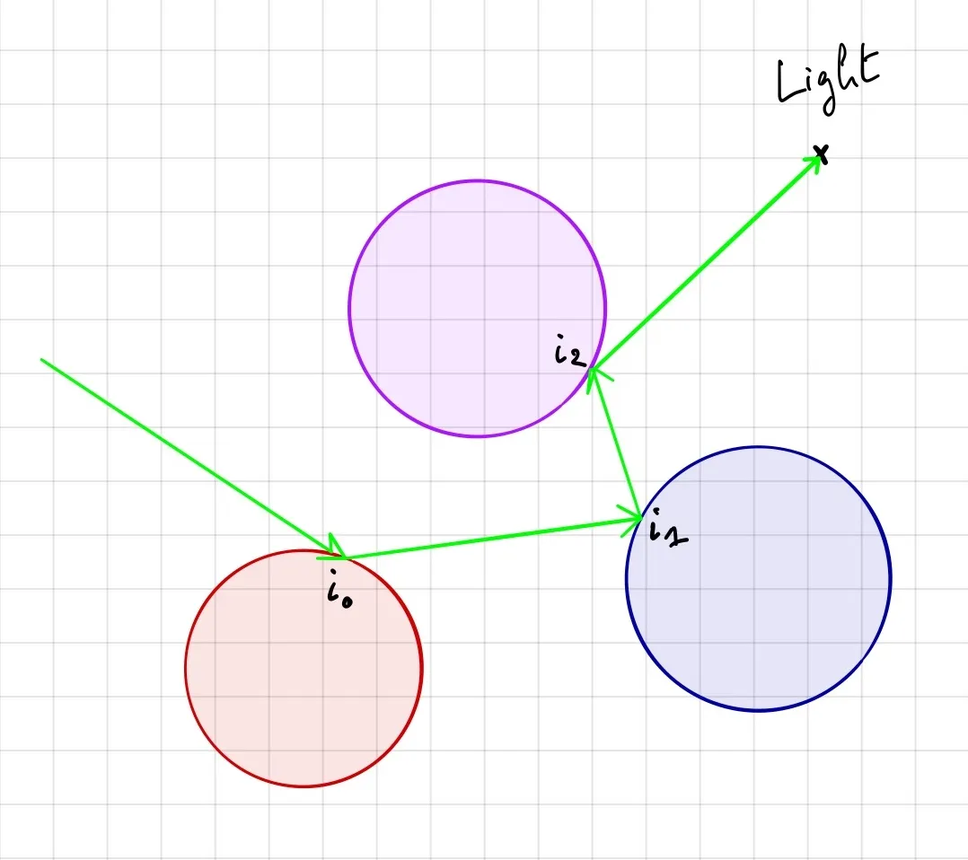
To include reflections, we need to trace the reflected ray after an intersection happen and include the color contribution of each intersection point. We repeat that process some number of time (to define). The final color of a pixel is the sum of the contribution of each intersected point by the ray.
Where,
- [begin-latex-inline]c_p[end-latex-inline] is the final color of the pixel
- [begin-latex-inline]i_k[end-latex-inline] is the illumination computed for the [begin-latex-inline]k^{\text{th}}[end-latex-inline] intersection point
- [begin-latex-inline]r_k[end-latex-inline] is the reflection of the [begin-latex-inline]k^{\text{th}}[end-latex-inline] intersected object
Then it's up to you to decide when to stop computing that sum (i.e. when to stop tracing reflected rays).
Reflected Ray
Before we can implement this, we need to find the reflected ray direction. We can compute a reflected ray the following way:
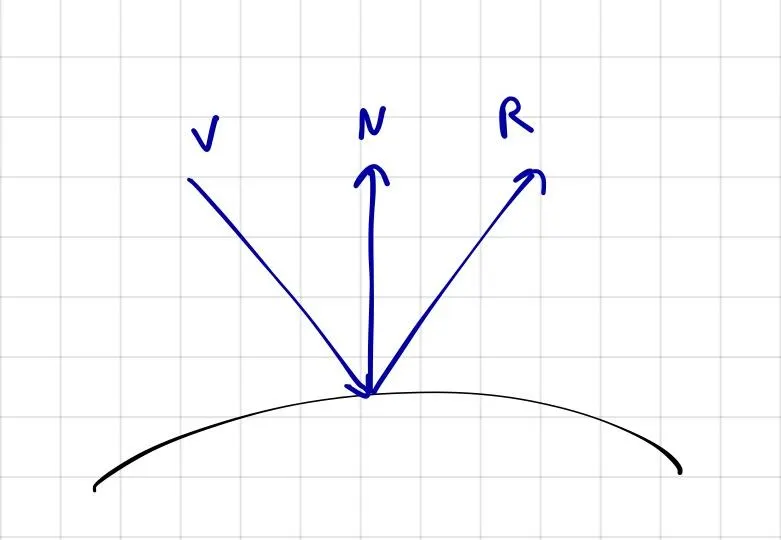
Where,
- [begin-latex-inline]R[end-latex-inline] is the unit-vector reflected ray
- [begin-latex-inline]V[end-latex-inline] is the unit-vector incoming ray to be reflected
- [begin-latex-inline]N[end-latex-inline] is the unit-vector normal to the surface stroke by the ray
def reflected(vector, axis):
    return vector - 2 * np.dot(vector, axis) * axis
Code
It's actually a small change at the end:
# global variable along with width, height, etc.
max_depth = 3

# everything that follows is inside the double for loop
color = np.zeros((3))
reflection = 1

for k in range(max_depth):
    nearest_object, min_distance = # ...
    # ...
    illumination += # ...

    # reflection
    color += reflection * illumination
    reflection *= nearest_object['reflection']

    # new ray origin and direction
    origin = shifted_point
    direction = reflected(direction, normal_to_surface)

image[i, j] = np.clip(color, 0, 1)break statements where we previously used continue statements to avoid useless computations.Final Code
The final code is surprisingly small, about a hundred lines of code!
import numpy as np
import matplotlib.pyplot as plt


def normalize(vector):
    return vector / np.linalg.norm(vector)


def reflected(vector, axis):
    return vector - 2 * np.dot(vector, axis) * axis


def sphere_intersect(center, radius, ray_origin, ray_direction):
    b = 2 * np.dot(ray_direction, ray_origin - center)
    c = np.linalg.norm(ray_origin - center) ** 2 - radius ** 2
    delta = b ** 2 - 4 * c
    if delta > 0:
        t1 = (-b + np.sqrt(delta)) / 2
        t2 = (-b - np.sqrt(delta)) / 2
        if t1 > 0 and t2 > 0:
            return min(t1, t2)
    return None


def nearest_intersected_object(objects, ray_origin, ray_direction):
    distances = [
        sphere_intersect(obj['center'], obj['radius'], ray_origin, ray_direction)
        for obj in objects
    ]
    nearest_object = None
    min_distance = np.inf
    for obj, distance in zip(objects, distances):
        if distance is not None and distance < min_distance:
            min_distance = distance
            nearest_object = obj
    return nearest_object, min_distance


width = 1600
height = 900

max_depth = 3

camera = np.array([0, 0, 1])
ratio = float(width) / height
screen = (-1, 1 / ratio, 1, -1 / ratio)  # left, top, right, bottom

light = {'position': np.array([5, 5, 5]), 'ambient': np.array([1, 1, 1]), 'diffuse': np.array([1, 1, 1]), 'specular': np.array([1, 1, 1])}

objects = [
    {'center': np.array([-0.2, 0, -1]), 'radius': 0.7, 'ambient': np.array([0.1, 0, 0]), 'diffuse': np.array([0.7, 0, 0]), 'specular': np.array([1, 1, 1]), 'shininess': 100, 'reflection': 0.5},
    {'center': np.array([0.1, -0.3, 0]), 'radius': 0.1, 'ambient': np.array([0.1, 0, 0.1]), 'diffuse': np.array([0.7, 0, 0.7]), 'specular': np.array([1, 1, 1]), 'shininess': 100, 'reflection': 1},
    {'center': np.array([-0.3, 0, 0]), 'radius': 0.15, 'ambient': np.array([0, 0.1, 0]), 'diffuse': np.array([0, 0.6, 0]), 'specular': np.array([1, 1, 1]), 'shininess': 100, 'reflection': 0.5},
    {'center': np.array([0, -9000, 0]), 'radius': 9000 - 0.7, 'ambient': np.array([0.1, 0.1, 0.1]), 'diffuse': np.array([0.6, 0.6, 0.6]), 'specular': np.array([1, 1, 1]), 'shininess': 100, 'reflection': 0.5}
]

image = np.zeros((height, width, 3))
for i, y in enumerate(np.linspace(screen[1], screen[3], height)):
    for j, x in enumerate(np.linspace(screen[0], screen[2], width)):
        # screen is on origin
        pixel = np.array([x, y, 0])
        origin = camera
        direction = normalize(pixel - origin)

        color = np.zeros((3))
        reflection = 1

        for k in range(max_depth):
            # check for intersections
            nearest_object, min_distance = nearest_intersected_object(objects, origin, direction)
            if nearest_object is None:
                break

            intersection = origin + min_distance * direction
            normal_to_surface = normalize(intersection - nearest_object['center'])
            shifted_point = intersection + 1e-5 * normal_to_surface
            intersection_to_light = normalize(light['position'] - shifted_point)

            _, min_distance = nearest_intersected_object(objects, shifted_point, intersection_to_light)
            intersection_to_light_distance = np.linalg.norm(light['position'] - intersection)
            is_shadowed = min_distance < intersection_to_light_distance

            if is_shadowed:
                break

            illumination = np.zeros((3))

            # ambiant
            illumination += nearest_object['ambient'] * light['ambient']

            # diffuse
            illumination += nearest_object['diffuse'] * light['diffuse'] * np.dot(intersection_to_light, normal_to_surface)

            # specular
            intersection_to_camera = normalize(camera - intersection)
            H = normalize(intersection_to_light + intersection_to_camera)
            illumination += nearest_object['specular'] * light['specular'] * np.dot(normal_to_surface, H) ** (nearest_object['shininess'] / 4)

            # reflection
            color += reflection * illumination
            reflection *= nearest_object['reflection']

            origin = shifted_point
            direction = reflected(direction, normal_to_surface)

        image[i, j] = np.clip(color, 0, 1)
    print("%d/%d" % (i + 1, height))

plt.imsave('image.png', image)
What's Next ?
This was a very simplistic program that was meant to educate on the subject. There are so many ways to improve this and implement other fascinating functionalities. Here are some of them:
- OOP! Right now we've put all the objects in a dict, but you could make classes, figure out what's specific to spheres and what's not, make a base class, and implement other objects such as planes or triangles
- Same thing goes for light. Add some POO here and make it so you can add multiple lights in the scene
- Separate the material properties from the geometrical properties, so you can apply one material (e.g. blue matte) to any object
- Figure out a way to position the screen correctly given any camera position and a direction to look at;
- Model the light differently. Currently it's a single point, which is why the shadows of objects are "hard". To get softer shadows, you need to model a light like a 2d or 3d object: disk or sphere?
Bonus
Here's an animation I made with ray tracing. I simply rendered the scene several times with the camera at different positions.